AM / FM MODULATION MONITORS
Model 520 AM Modulation Monitor
![]()
Mono-AM Modulation Monitor with built-in preselector.
Accurate off-air modulation measurements.
Remote alarms for overmodulation, carrier-loss and program-loss.
The Model 520 is a compact and accurate AM Modulation Monitor with a bright, easy-to-read display. In addition to one pair of peak flashers preset at the –100% and +125% absolute-modulation limits, a second pair of flashers may be user-set at alternative trip points. Alarm tallies are available on the rear panel, and an RS-232 port allows data logging by computer or modem.
________________________________________________
Model 531 FM Modulation Monitor
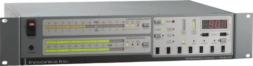
Built-in preselector for precise off-air measurements.
Seven station presets may be recalled by remote control.
Bright, accurate bargraph metering:
- Total Modulation
- Stereo Program Audio
- Subcarrier Injection
- Incidental AM Noise
- Signal Strength and Multipath
Alarm tally outputs for remote fault indicators.
Incorporating all the necessary features at a very affordable price, Inovonics’ 531 is the undisputed value leader in an FM Mod-Monitor. Dependable off-air monitoring lets you keep an eye on other stations in the market as well as measuring the important parameters of your own signal. High-resolution bargraph displays are easy to read, and a “floating dot” program peak marker eliminates any ambiguity in the total-mod measurement. Off-air readings are qualified by Inovonics’ exclusive multipath indicator, which also aids in antenna alignment.
______________________________________________________
Model 540 FM Sub Carrier Modulation Monitor
![]()
A tunable monitor for all digital and analog FM subcarriers.
Measures sub injection level and demodulates SCAs.
Optional RS-232 interface for downloading RDS/RBDS data.
The Model 540 connects to the composite/MPX output of any FM modulation monitor. Setup is simplified with a built-in calibration utility. The 540 is tuned in 1kHz steps to display the injection level of any digital or analog subcarrier between 55kHz and 99kHz. A dual-bandwidth IF accommodates wide and narrow subcarrier signals. Conventional analog SCAs are demodulated to show the actual subcarrier deviation, and an RS-232 interface is optionally available for downloading and reading RDS/RBDS data groups.
_________________________________________________
Model 510 RDS/RBDS Decoder - Reader
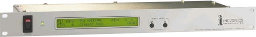
Decoder/reader for RDS/RBDS.
Displays all radio-data groups: flags, codes, radiotext, etc.
Accurate digital readout of subcarrier injection level.
The Inovonics 510 connects to the composite/MPX output of any FM receiver or modulation monitor to display all the RDS/RBDS radio-data groups. The backlighted LCD readout displays station, format and program IDs, alternative frequencies, text and in-house messages, traffic and emergency alerts, plus the subcarrier injection level in percent-modulation. A rear-panel RS-232 port allows further analysis or archiving of received data. The 510 conforms to European CENELEC and American NRSC standards.
______________________________________________________
When You Need Everything In Your FM Modulation Monitor...
Model 691
Stereo FM Modulation Monitor/Test Set
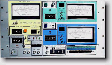
The 691 FM Modulation Monitor/Test Set is a high technology, precision instrument employing a combination of new techniques in a single, highly versatile, but very compact package. It has been designed to be a complete FM test package with facilities for all proof-of-performance measurements and a wide range of trouble-shooting tests. Operator convenience and simplicity of use were primary considerations in the design of the 691. Component selection and device ratings are such as to enhance the instrument's reliability even with adverse handling. The 691 occupies only 10-1/2 " of vertical rack space in a standard 19" rack.
_________________________________________________
A Short List Of Features:
A Complete Proof-of-performance Instrument For Mono, Stereo And SCA Measurements
Tunable In 100 KHz Steps Over The Entire FM Band
Auto-Ranging Meters Select Correct Meter Operating Range Automatically
Converts A Standard X-Y Oscilloscope Into A Spectrum Analyzer For Occupied Bandwidth Observations
Off-The-Air Or Direct Transmitter Connection
Will Accept Up To 50 Watts Of RF Input With A Suitable Load Termination
Functional Front Panel Layout With Color Coded Groupings And Unique Over-under Meter Arrangement
Extremely Low Internal Distortion
Peak Flasher Adjustable From 1% To 199% With Digitally Displayed Peaks Per Minute
Vector Display Of Stereo Phasing With Standard Oscilloscope
Composite Input Allows Direct Measurement Of The STL Receiver, Stereo Or SCA Generator Output
Over Forty Proof-of-performance And Trouble-shooting Tests Possible When Used With An Oscilloscope
Built-in Modulation Calibrator
Built-in Bessel Null Feature Allows Field Calibration Verification
Full One Year Warranty On All Parts And Labor
Front Panel Convenience
A color coded grouping system ties together the associated meters, switches, indicators and jacks for a particular test or function. This coupled with the auto-ranging metering and front panel indicators minimize operator error. Adding to these ease-of-operation features is the simple but effective device of mounting the L and R meters vertically thus eliminating the "Ping-Pong" type of eye movements necessary for horizontally mounted meters. Both the 691's meters are easily tracked in a single glance.
Easy-to-operate
In addition to the functional color coding a number of features are incorporated into the 691 that simplify operation and maximize accuracy. The RF input level is monitored and the signal level displayed by 3 LED's (HI-LO-OK). Calibration can be verified from the front panel. A single row of push-buttons simultaneously select both A and B displays of the two auto-ranging meters. All primary test outputs are available on the front panel (BNC jacks). The signal inputs and secondary outputs are located on the rear panel.
Color coded lamps indicate pilot and/or sub-carrier presence. A warning LED illuminates should the local oscillator become unlocked. The operating frequency and peak flashers are set by use of rugged thumb wheel switches to assure positive contact and minimize setting error.
Monitor Pilot phase may be matched to stereo generator pilot phase in the presence of modulation.
Test Set Flexibility
The built-in signal sampler allows the 691 to function as a self-contained exciter test set. Any exciter of less than 50 watts output may be directly connected to the RF input thereby eliminating the requirement and expense of external signal samplers. All required frequency outputs are available at a single (switch selectable) front panel BNC connector.
The front panel outputs of the test meters allow quick and easy oscilloscope-comparison of channel A and channel B content when making separation, crosstalk, or noise measurements.
The null setting for stereo generator (19 kHz-38 kHz) phase increases accuracy and reduces test equipment set up time.
FM noise and AM noise measurements are made automatically without the need to preset reference levels.
The 691 comes complete with a six element Yagi antenna for off-air monitoring eliminating the need for an additional amplifier.
Autoranging Test Meters
A "display-select" row of push-buttons choose seven (7) pair of different tests (14 total) to be displayed by the Auto-ranging Meters. Channel A is displayed on the upper meter while channel B is displayed on the meter directly below it. Channel A and B meters will automatically select and indicate in the correct operating range for the level of signal under test. The operating range and unit of measurement is displayed directly to the left of its respective meter. The meters are individually selectable to display either positive or negative peaks.
The autoranging feature can be defeated by a front panel switch which allows the meter to function with the ballistics specified by the FCC when these types of measurements are required. The de-emphasis network can be activated by a push-button switch conveniently placed to the left of the meter.
AM noise and FM noise measurements automatically activate the de-emphasis network.
Spectrum Analyzer And Vector Display
The 691 provides two BNC jacks for X-Y connection to an oscilloscope (not supplied with 691). A front panel push-button selector enables the operator to view the occupied bandwidth of the transmitters signal with either a 240 kHz or 700 kHz display. The 240 kHz (narrow) spectrum analyzer display allows the operator to use bessel null functions to determine the absolute calibration accuracy of the 691 Monitor/Test Set.
Additionally the phase relationship between the left and right channels may also be viewed on the oscilloscope as a vector display. This simplifies stereo phase adjustment and allows continuous monitoring of the phase relationship of an off-the-air signal.
Peak Flashers And Counters
The total modulation flasher illuminates each time the level of modulation exceeds a pre-determined level (adjustable from 0 to 199%). The total modulation peaks exceeding this level in a one minute period are counted and displayed. LED peak flashers, also adjustable, are used for channel A and B displays.
Available as a low cost option is the Variable Peak Detection card, which allows the end user to select the peak weighting (interval) and number of peaks within a specified time period.